The MiTek Hardy Brace Frame resists lateral loads in both tension and compression.
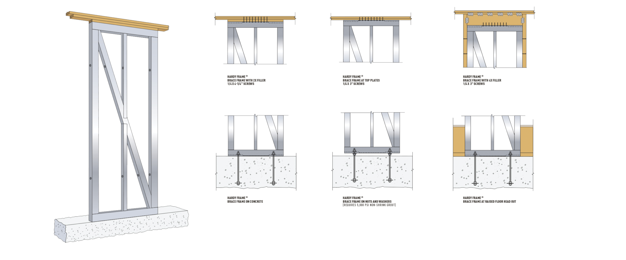
MiTek Hardy Brace Frame on Concrete Foundations
- Installation on nuts and washers provides for leveling at uneven concrete – open end box wrench may be used to secure connection from below. Confirm with design building professional prior to installation.
- Raised floor head out by passes wood framing to eliminate the effects of shrinkage and crushing, while providing a direct shear transfer to the foundation
- Raised floor head out requires less material by eliminating the rim and bottom screws
- The new HFX-Series Brace Frame has relocated hold down bolts to be outside of the post. Hold down connections are now accessible even when wood or framing is incontact with the edge of the frame.
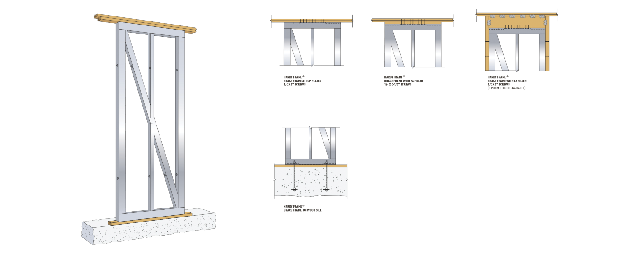
MiTek Hardy Brace Frame on Wood Sill
- Brace Frames installed on wood sill plates have more ductility but, for some sizes the allowable shear is less to account for crushing of wood below
- Allowable values have been reduced when necessary to maintain code drift limit (see HFX-Series Product Catalog Table 1.2)
- Because the Brace Frame base is wider, overturning forces cause less compression on wood sill.
Installation:
- Set bolts 4-1/4″ inches above concrete
- Moisture barrier (15# felt, Moist Stop, Etc.) recommended when installing on treated wood
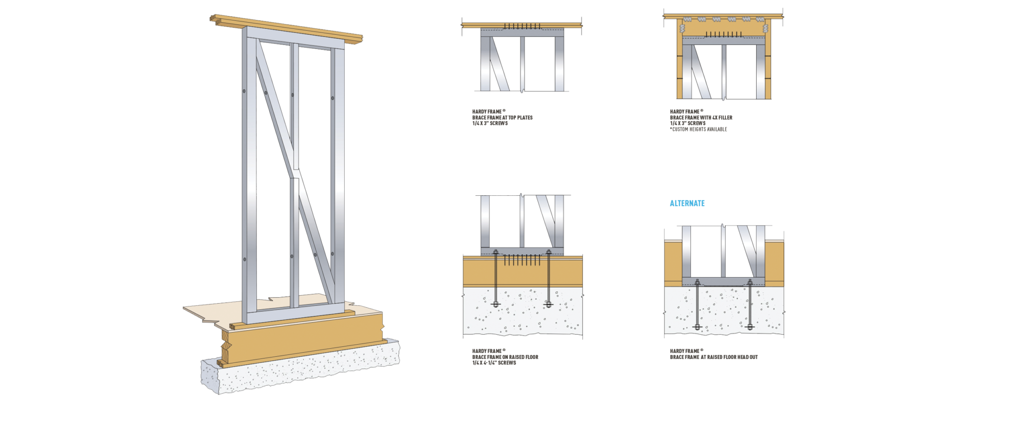
MiTek Hardy Brace Frame on Raised Floor
- Allowable values have been reduced when necessary to maintain code drift limit (see HFX-Series Product Catalog Table 1.3)
- Raised floor head out installations by pass wood framing to eliminate the effects of shrinkage and crushing, while providing a direct shear transfer to the foundation
- Table values for Panels installed on a wood floor system assume installation with a MiTek Hardy Bearing Plate
Installation at raised floor head-out:
- Provides allowable values from HFX-Series Product Catalog Table 1.2A
- Provides a direct shear transfer to the foundation
- Requires less material by eliminating rim, Bearing Plate and bottom screw
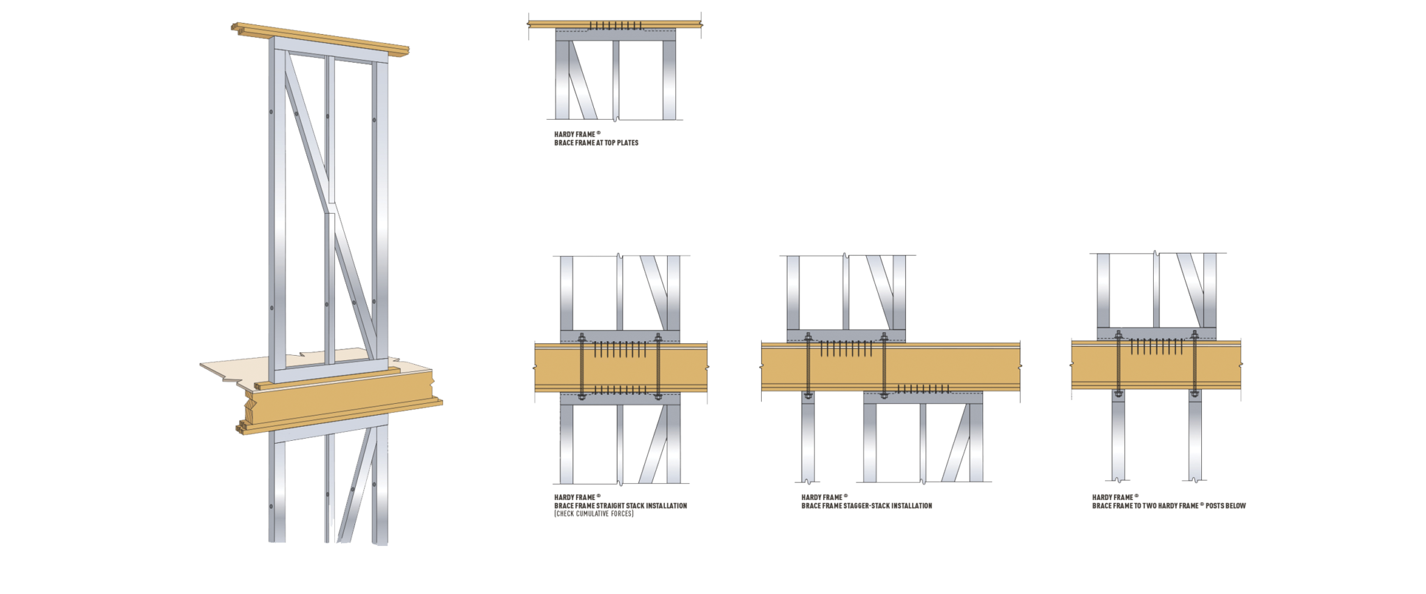
MiTek Hardy Brace Frame on Upper Floor
- Allowable values in HFX-Series Product Catalog Table 1.3A have been adjusted to maintain code drift limit while including the effects of crushing in wood members below
- For “straight stack” installations cumulative forces must be considered by the building design professional
- For discontinuous systems amplification factors must be considered by the building design professional
- For installation on beams, size plate washers on underside of wood beam to prevent crushing and include deflection from the overturning couple in the drift procedure
- Because Brace Frames are wider, overturning forces cause less compression on wood below and shrinkage has less effect on horizontal drift.
- Unlike Panels, Brace Frames install on the bottom plate above floor systems. MiTek Hardy Bearing Plates are not necessary.
MiTek Hardy HFX/S-Series for Cold Formed Steel (cs-f) Framing
- HFX/S Series products are manufactured to cold formed steel stud heights. Nominal 8’ heights are 96 5/8˝ net, nominal 9’ is 108 5/8˝ , etc.
- Installation can be directly on concrete (moisture barrier recommended), with a c-fs channel below, or a nut and washer for eveling or height adjustment up to ± 1/2˝
- Top connections are made with 1/4˝ diameter self tapping screws after installing floor or roof members above.
- Brace Frames are 3 1/2˝ net depth.
- The new HFX-Series Brace Frame has relocated hold down bolts to be outside of the post. Hold down connections are now accessible even when wood or framing is in contact with the edge of the frame.


