Hardy Moment Frames
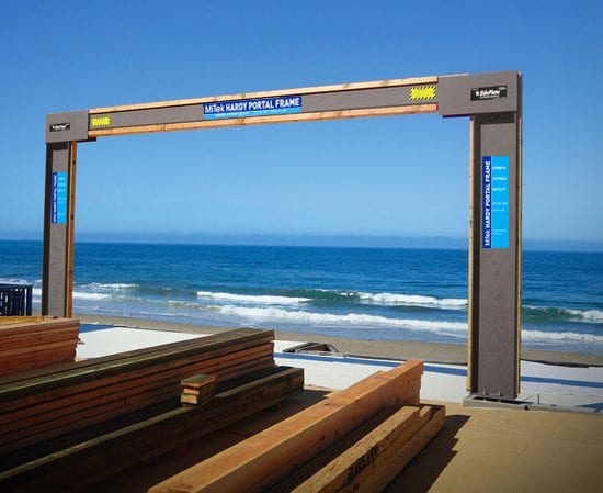
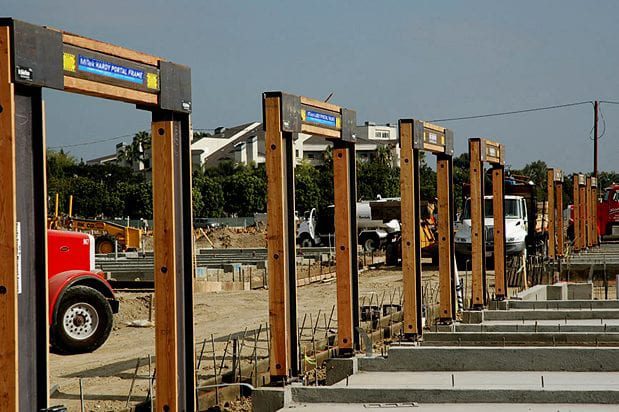
No field assembly. No site bolting. No field welding – unless you want to. If you’re designing structures for high wind and seismic loads, there is no better frame.
MiTek Hardy Moment Frame Overview

When to use a Hardy Portal Frame:
- At large openings where the narrowest wall space is available and high shear loads are required.
- When foundations are limited or existing and a pinned base connection facilitates foundation design.
- When designing three story or greater structures, all parallel walls must be designed at the lowest R-Value. Specify a Hardy Portal Frame and design at the same R=6.5 as design of plywood shear walls.
Hardy Picture Frame:
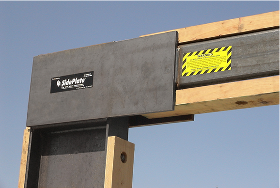
- Doubles the capacity of a typical Hardy Portal Frame with SidePlate SMF Connection at four-column intersections.
- Maximize frame capacity with the most economical column and beam sections.
- Designed to significantly increase lateral force capacity and reduce earthquake deformation.
- Built-in Hollow Structural Steel section replaces the need for complex grade beam design and eliminates associated field labor and material.
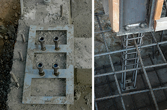
- Pinned Base Anchorage requires minimal footing size.
- Pre-Assembled, Pre-welded for fast installation and quality control. Option for bolted splice is available.
Designing for New Construction:
- Calculate the design shear load based on an R-Value of 6.5.
- Select a Hardy Portal Frame based on the required geometry from standard tables.
- Check that the tabulated Allowable Shear meets the design shear load.
- If the design shear load exceeds the allowable table value, contact MiTek to determine if an alternate solution, such as a “fixed base” connection will meet the design loads.
- Calculate the additional vertical loads using the IBC strength design load combinations.
- Check that additional vertical loads do not exceed the tabulated Allowable Vertical Loads.
- Calculate the tabulated Column Base Reactions for use in the foundation design.


Specification:
On the Foundation Plan
- Specify the Hardy Portal Frame model number at the location to be installed.
- Specify anchorage designation for tension and shear from Hardy Portal Frame Anchorage table in MiTek Hardy Portal Frame detail sheets.
- Specify connection of column base to the foundation (on Nuts & Washers, on Concrete, with Pinned or Fixed Base) refer to Installation Details for connections.
Specification:
On the Framing Plan
- Specify a connection from the collector (or “drag”) to the top of the Hardy Portal Frame from Installation Details.
- Consider out of plane bracing for the Frame either through a diaphragm to the beam or with framing members to the columns.

Submittal Documents Provided by MiTek
- A calculation package for the model number specified.
- Installation Detail Sheets for inclusion as “supplemental plan pages.”
Additional Items:
- The table values for Allowable Shear Loads assume Pinned Base anchorage.
- When additional shear load or a drift limit less than the code maximum is needed a Fixed Base design is available. Consult with Hardy Frames to determine fixed base values and options.
- All allowable shear loads have been adjusted to an R-Value of 6.5. To convert design loads from R=3.5 to R=6.5, multiply the design load by 3.5/6.5.
- The allowable shear loads are based on a story drift of 0.025h. To convert shear loads to a story drift of 0.020h multiply the table value by a factor of 0.8.
- When designing lateral resistance for a wall line with varying shear resisting elements the stiffness (drift/allowable shear load) must be proportioned.
- Two story Portal Frames are available. Fill out the Non-Standard Worksheet at the back of this catalog and submit to MiTek to check the required configuration and loading.
